
Controlling dimensions in Inkscape
Controlling dimensions in Inkscape
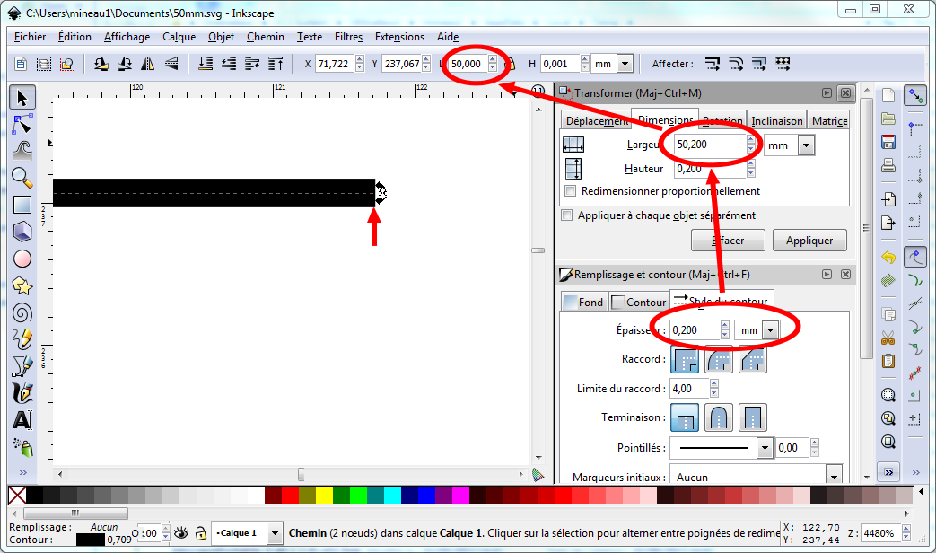
Table of contents :
Controlling dimensions in Inkscape
Inkscape is an excellent vector graphics software. I use it very often for the most artistic parts of my technical drawings, each time that I need to find the nice curve …
But at the end of the day, it is anyway necessary to master the dimensional aspect of the drawing, especially if you want to import it in Qcad for instance.
Now, Inkscape has a very irritating defect, precisely concerning dimensions.
I will try to explain the behaviour of Inkscape, and to give some elements allowing to master a little bit better the dimensions in that software.
The irritating thing
Let’s take an example : You want to create an horizontal line, exactly 50 mm long and of 0.5 mm width.
You take the “Bezier curves and straight lines " tool, you put the first point, you press CTRL and you place the second point at an approximate distance from the first, and then you press Enter to end the segment.
Then you select the segment, and in the selection toolbar, you want to force 50 mm as the length.
1st issue: It doesn’t obey you, and gives a segment of 50.095 mm
length.

Second attempt, you re-enter 50 mm : now you obtain 50.001 mm.
Third attempt, you re-enter 50 mm : at last, you obtain 50.000 mm.

Let’s set now the width of the line : box “Fill and stroke”, Width= 0.500 mm
You see now that the height is rightly 0.5, but the length has again changed : 50.218 mm !

After two attempts, you eventually obtain a line 50.000 mm x 0.500 mm.

First conclusion : For some strange reasons, when you re-dimension an
object using the keyboard, you must make several attempts and persevere until
you reach the wanted dimensions … 
Let’s verify now the accuracy of our line in QCAD (see the
article).
Again, it is surprising : Our line is now only 49.5 mm long (we can spare it
the 0.022/1000) ! And our width has been lost, we now have in Qcad the default
width of the layer, and not the one set in Inkscape.

Explanation
Inkscape and Qcad have two different philosophies concerning the size of objects.
-
Inkscape : It takes into account the width of the contour stroke. The 50 mm line is indeed constituted of two nodes, 49.5 mm apart, with at each end, the width of half a stroke. So : 50=0.25+49.5+0.25.

The SVG format records, for that object, on one side, the nodes, and separately, the style of the stroke, including its width. One can have a look at the xml file to understand that.
Moreover, in the SVG file, the unit is the pixel, not the mm. It is the reason why you never retrieve exact numbers in millimeters.
Inkscape converts the dimensions set in millimeters into pixels, using a default resolution of 90 dpi (pixels per inch of 25.4mm). -
Qcad : Its SVG import function is quite rudimentary. It only takes into accound nodes.
It is the reason why our line is only 49.5 mm long. Its width is the default one from the layer into which the object has been imported and doesn’t take into account the styles in the SVG file.
The concept of Cap
In the “Fill and Stroke” box, Inkscape offers a way to specify how the line should end:


You can choose between “end on the stroke” or “end on the node” , rounded or square.
Beware : These modifications are only style modifications. That is to
say they do not modify the position of the nodes in the SVG file.
They are not taken into account if you import the file in QCAD…
The concept of bounding box
The “bounding box” is the rectangular selection box that surrounds the
selected objets.
In the selection bar, it is the dimensions of this box that are indicated with
the “W” and “H” parameters.
It is possible to specify in Inkscape two different behaviours of this bounding box :

-
The first is the “Visual” bounding box.
The selection includes the stroke width of the contours. -
The second option is the “geometric” bounding box.
In this case, the selection ends on the nodes of the object.
When you work with the goal of exporting your drawing towards QCAD, it is more interresting tu use that second option, so that you visualize the dimensions that will really be taken into account in QCAD, which are only depending of the position of the nodes.
The choice of the bounding box is set in the “File/Inkscape preferences/Tools” menu :

Note : When you use the “geometric” bounding box, it is no more possible to change the dimensions in the fields “W” and “H” of the selection bar. You must use instead the box “Object/Transform…/ Scale tab”. (see summary below)
Mastering the dimensions in Inkscape
To summarize, in order to master the lengths and dimensions in Inkscape, here are the steps you need to follow :
-
Configure Inkscape to use the “Geometric” bounding box : menu Fichier/Inkscape preferences/Tools
⇒The selection bar now indicates the dimensions as you will see them in QCAD. -
Draw the object (example: the above 50mm line)
-
Use the box Objet/Transform…/Scale tab to verify the exact dimensions, taking into account the width of the stroke.
The stroke width is the one specified in the box Objet/Fill and stroke … / Stroke Style tab.
⇒ If you choose a width of 0.2 mm, you need to add 0.2 mm to the object dimensions.
In this box, the specified dimensions are always taking into account the stroke width, whatever are the bounding box or cap settings.
Exemple :

Here you go, comments are welcome.
Christophe
Older readers comments
Hello from jC_Omega
Hello from CECCALDI_
Pour maîtriser les dimensions, d'un simple trait par exemple, on peut le manipuler avec l'outil "Editer les noeuds ou les poignées de contrôle d'un chemin (F2)". Avec cet outil la largeur du trait ne bouge pas quand on modifie ses extrémités.
Avec l'outil "Sélectionner et transformer des objets (F1)" la largeur évolue avec l'orientation du trait.
Cordialement
F.C.