
Homemade Nickel plating
Homemade Nickel plating
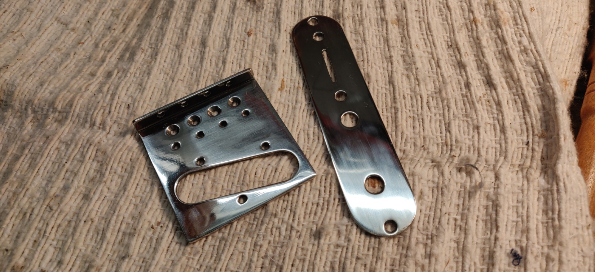
Table of contents :
Here is a method that allows you to perform nickel plating on small parts without resorting to complicated means,
and above all without using corrosive or dangerous chemicals other than household products.
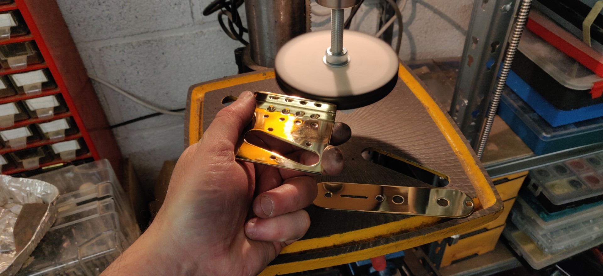
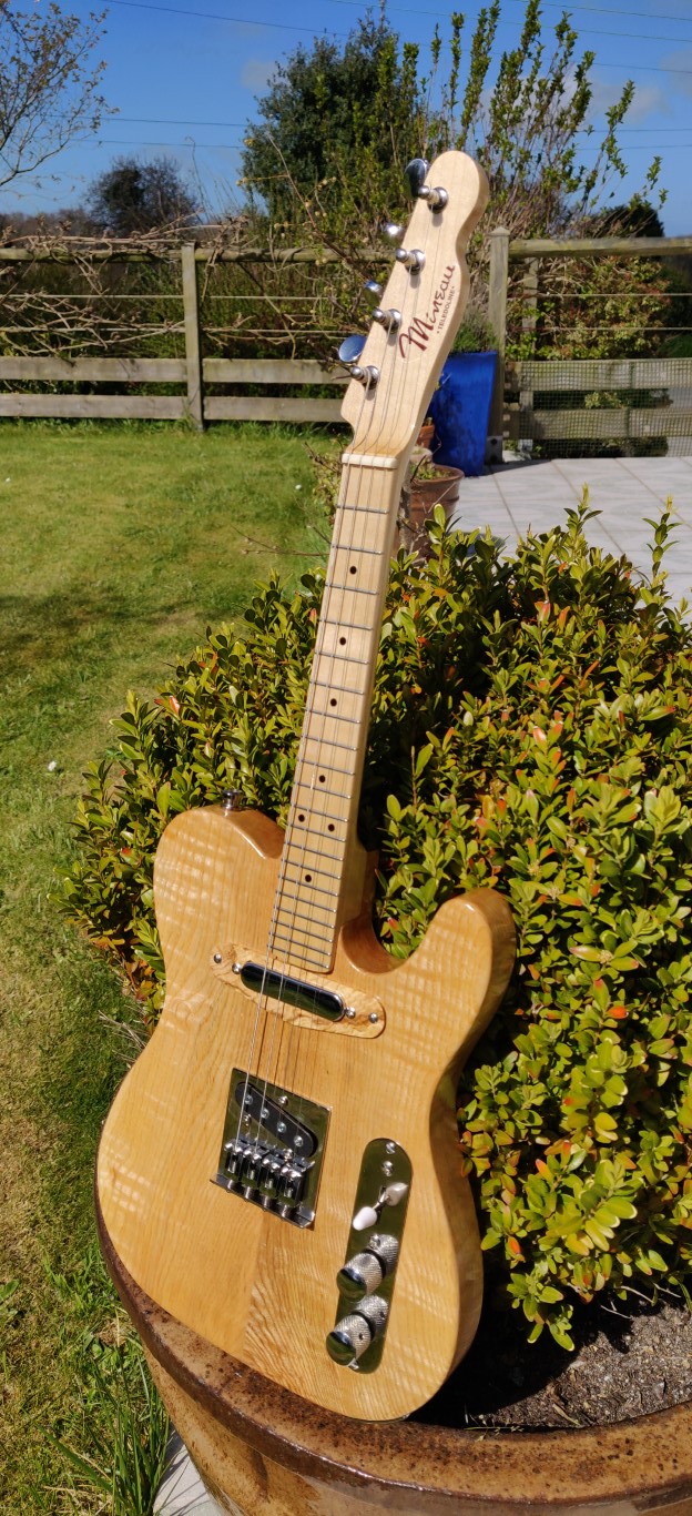
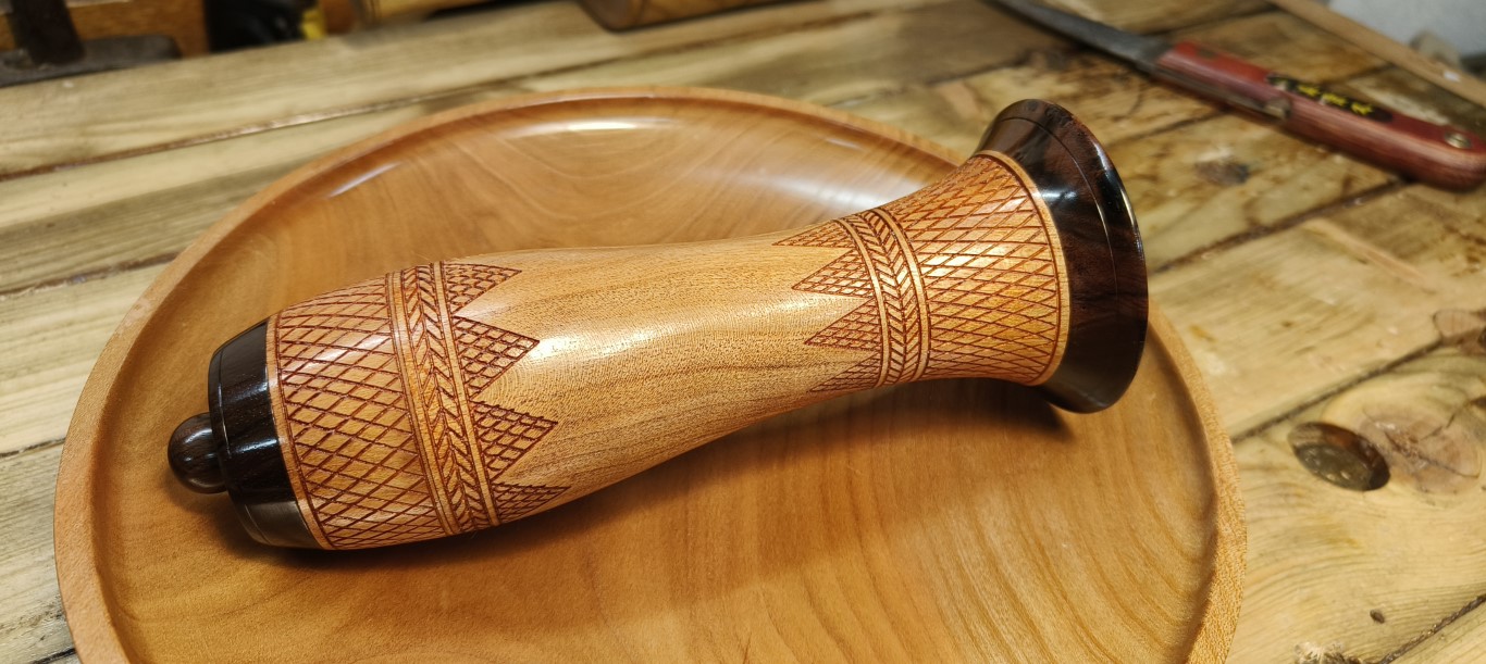
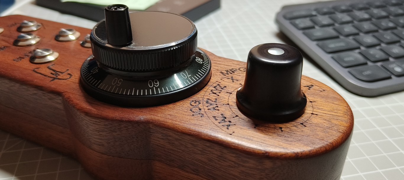
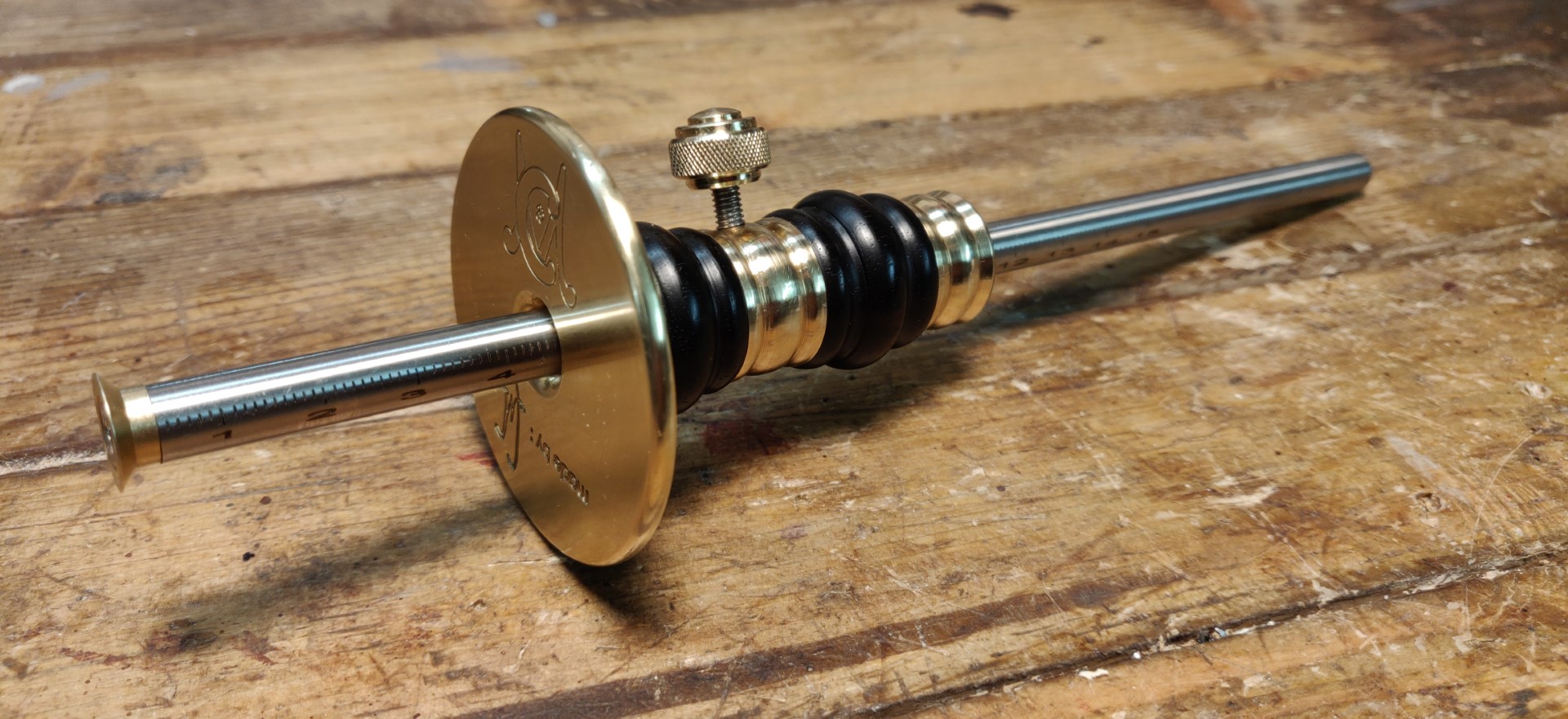
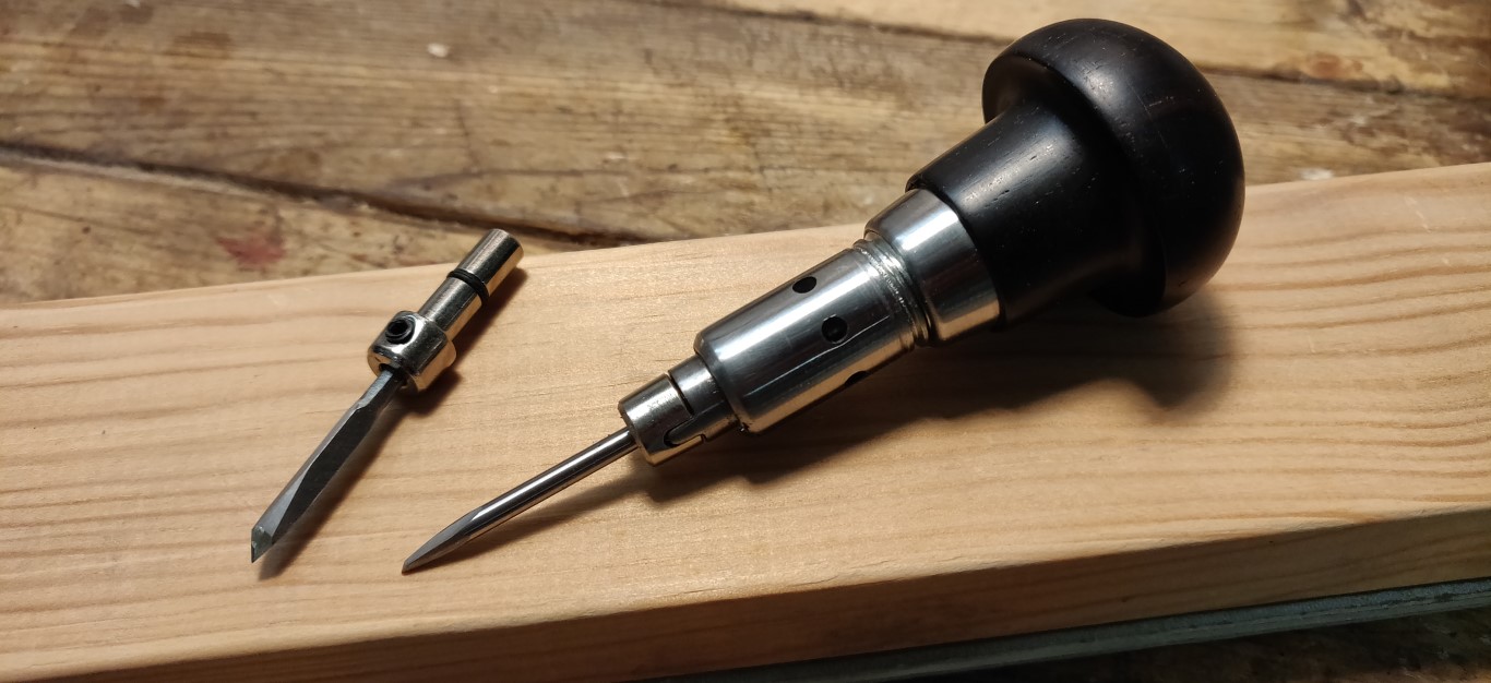
The parts shown in this example are hardware parts used on this mandolin.
What you need
What’s needed :
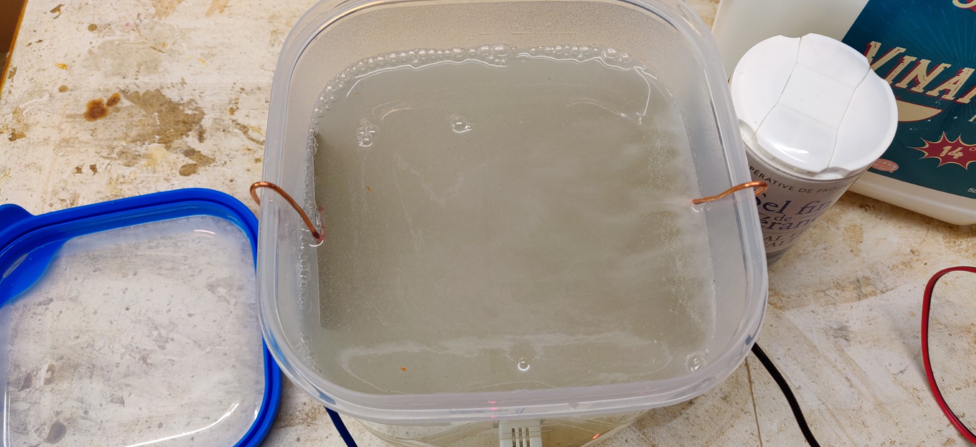
- A glass or plastic container with lid, I use a 2L container.
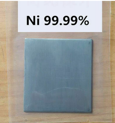
- A pure nickel sacrificial anode (ebay/amaz store).
- Household white vinegar, 14°.
- Salt (rather salt from a mine, salt from the sea has too much impurities in it).
- A variable power supply, ideally adjustable in current, capable of delivering 3 to 4 amps typically.
Preparing the electrolyte
The first phase consists of making the electrolyte. The same electrolyte bath can be kept and can be used again for other plating operations, as long as this bath remains clear and without impurities. During a plating, it is the anode that wears out and the electrolyte does not normally deplete.
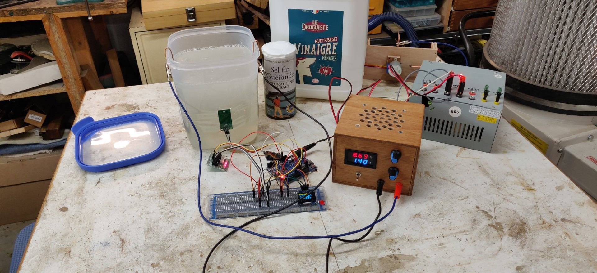
Setting up
To make the electrolyte, I used here about 1.5 liters of white vinegar at 14° in which I dissolve 1 level tablespoon of fine salt
per liter of vinegar.
Salinity increases the conductivity of the solution.
The pure nickel sacrificial anode is cut into 2 equal parts.
- A piece (anode) is connected to the + of the power supply
- the other piece (cathode) is connected to - the power supply.
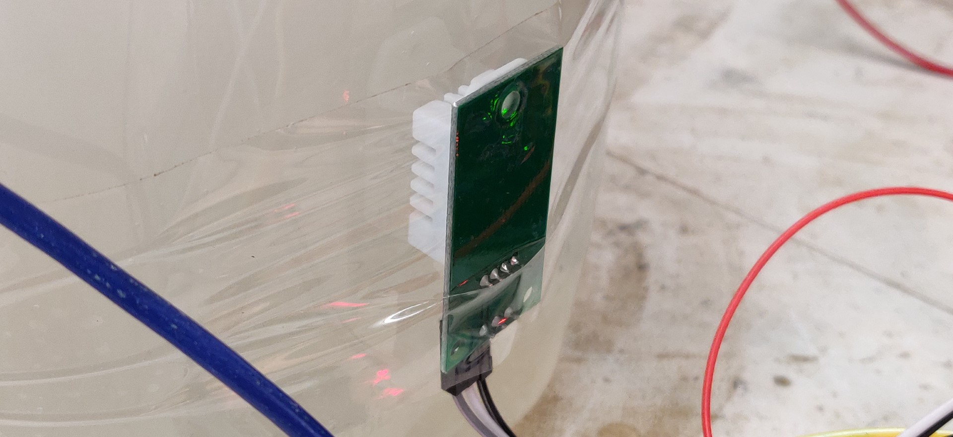
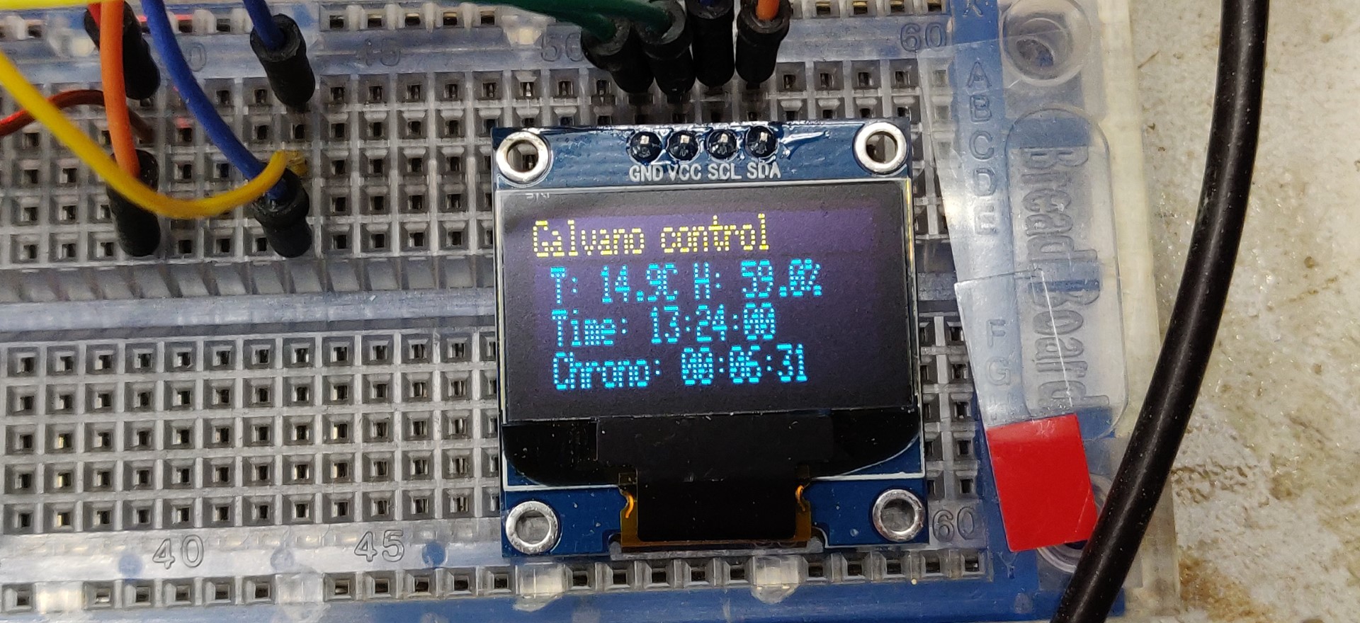
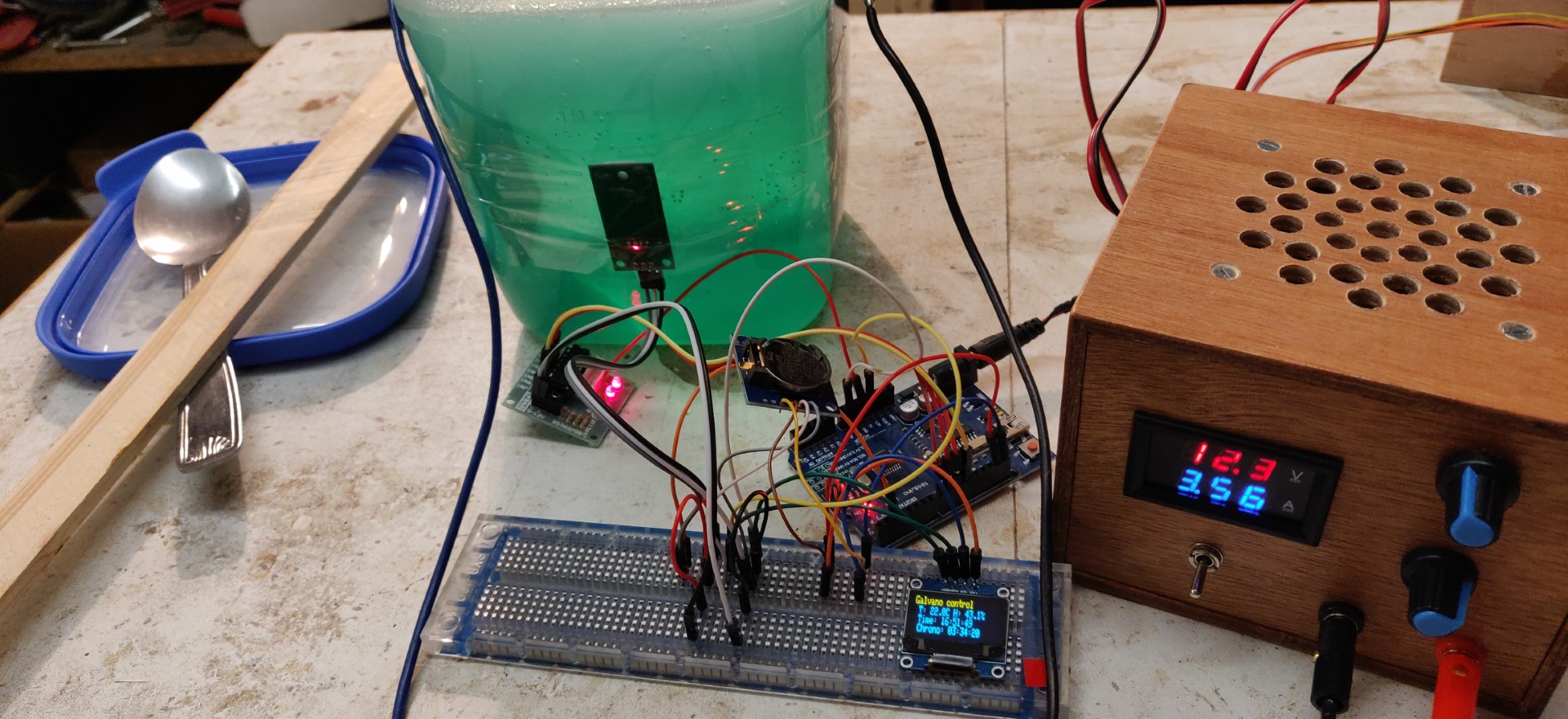
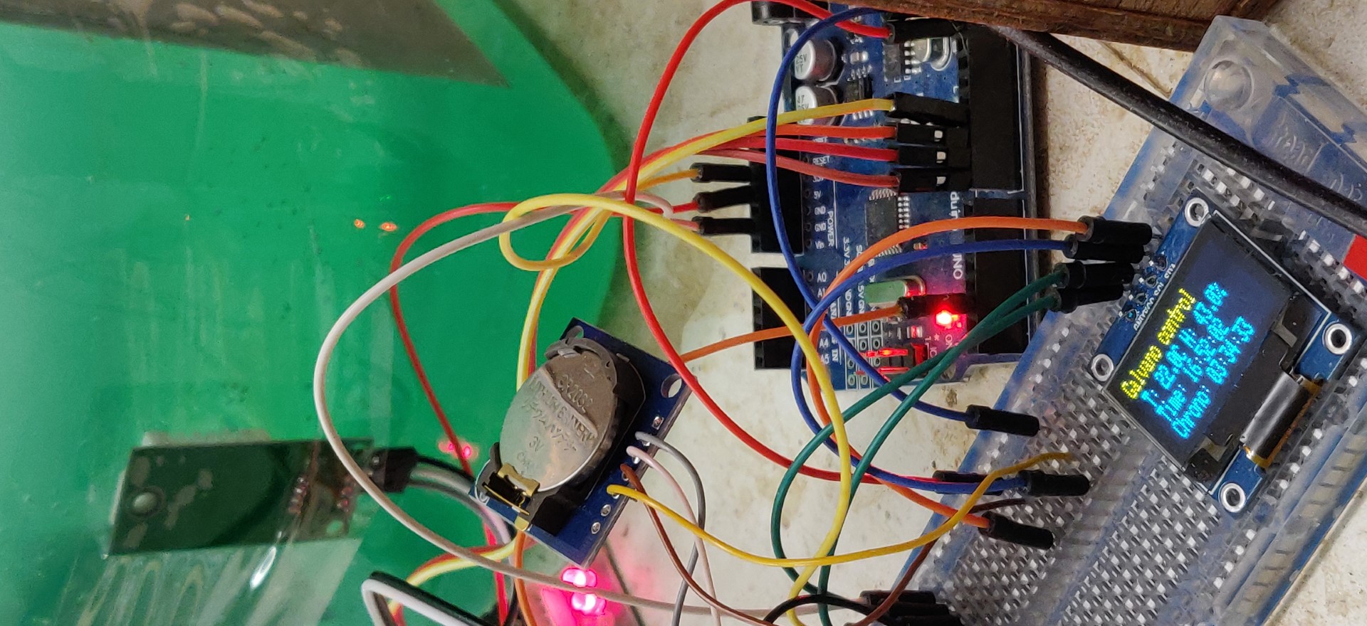
Note that in my case, I had fun controlling the temperature of the bath during the electrolysis. It’s actually useless, there is no significant temperature rise. I also checked the time elapsed in each phase, which is very useful. I will not detail this part which is optional.
Electrolysis
Nickel acetate electrolyte is obtained by electrolysis, i.e. by means of an electric current through the solution,
a transfer of nickel Ni atoms from the electrodes to the solution is obtained, which becomes loaded with Ni2+ ions.
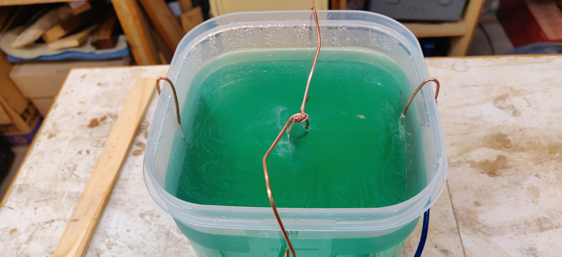
The solution, when enough populated with Ni2+ ions, takes on a nice green color.
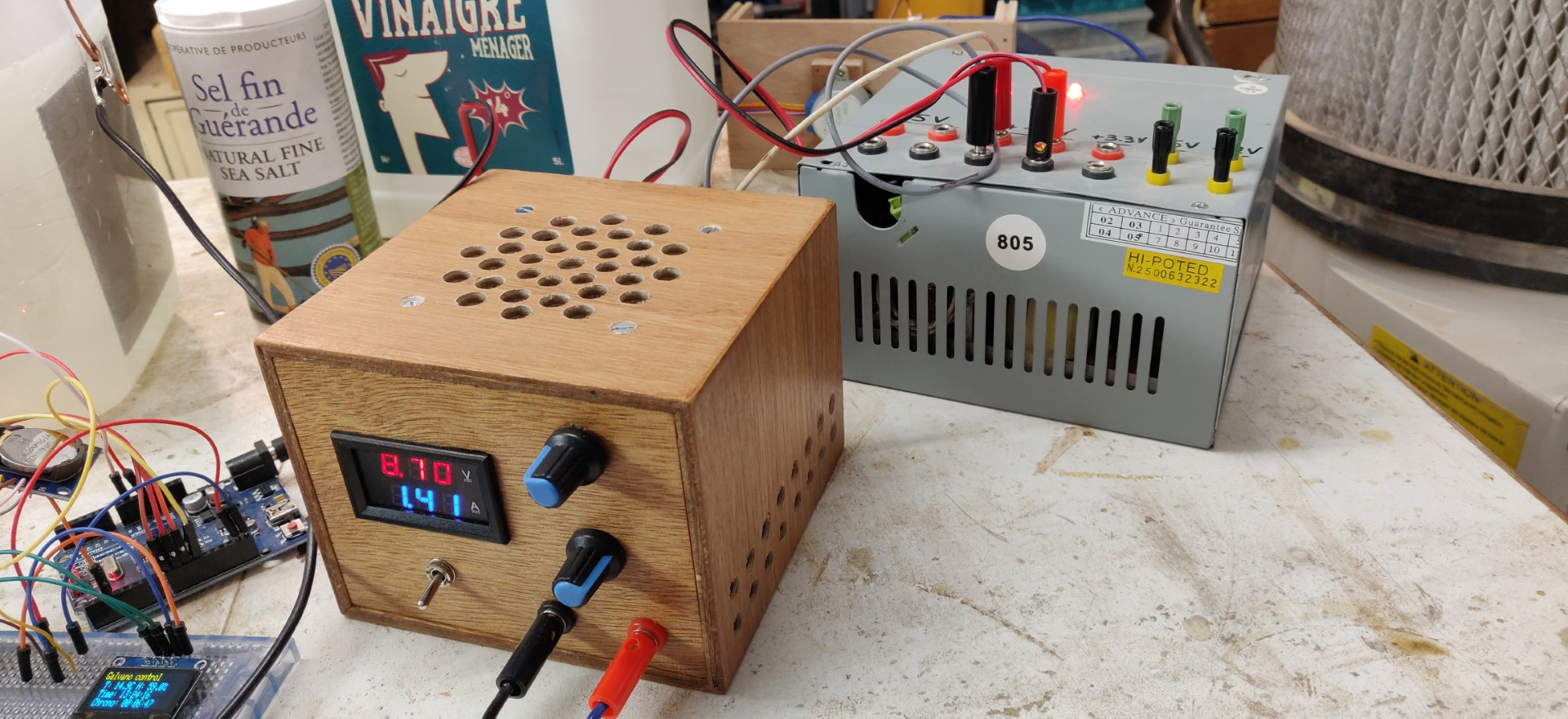
I use a variable current (0-10A) and voltage (0-30V) power supply. See build of this PSU here.
This variable power supply is supplied primarily by an ATX PC power supply (see also here).
In a first phase:
- Voltage around 9V
- which gave in my solution a current of about 1.5A. In truth, it is the amperage that is desirable, so aim for 1.5A instead and adjust the voltage as needed.
- duration 2h30
In a second phase, after 2h30:
- Voltage around 12V
- Current of about 3.5A
- duration of 1 additional hour
We are looking for a beautiful mint green color with water (but well concentrated in mint). In my case, I therefore stopped after 3h30.
At this stage the cathode looks like lace and is half disintegrated. Nickel atoms have become ions.
The obtained solution is nickel acetate.
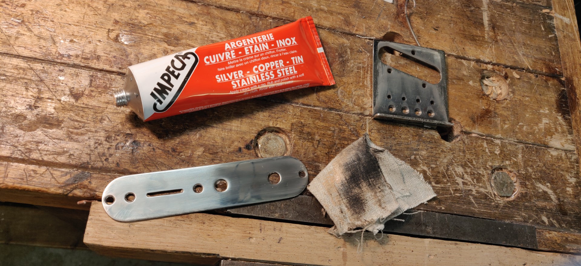
Preparing parts
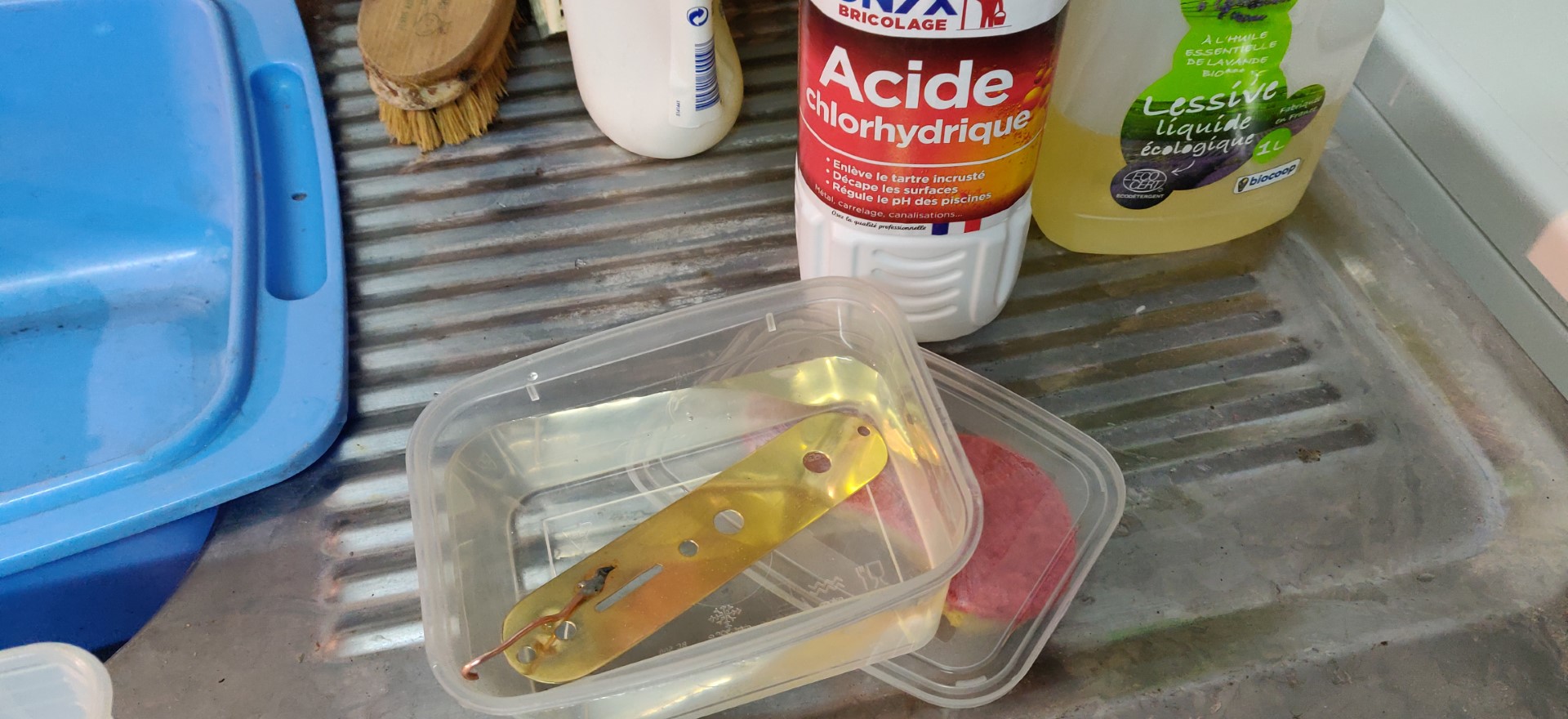
In my case, I will plate brass parts. It is imperative to sand and polish perfectly beforehand if you want to obtain a good result. Polishing must be followed by careful degreasing:
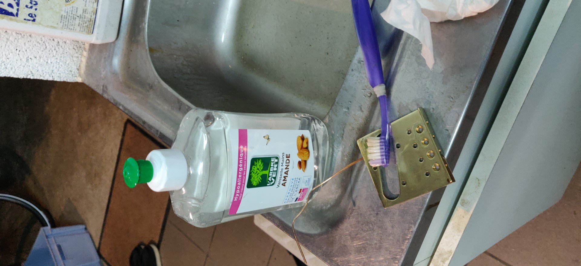
- washing with detergent
- bath in household hydrochloric acid, 5 minutes minimum. (Caution, be careful when handling acid, wear goggles and gloves!)
- rinse with clear water
After degreasing, the parts should no longer be handled with your fingers.
To facilitate the connection to electricity and the handling of parts,
I directly soldered before cleaning a copper wire on a part which will not be visible from the part.
Plating
Theory
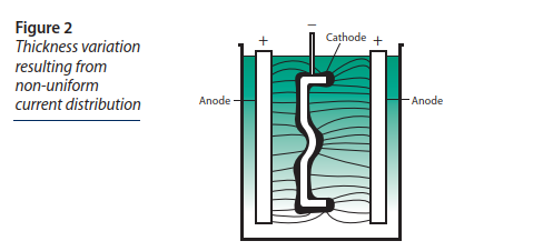
Here is the principle of the Nickel electro-plating:
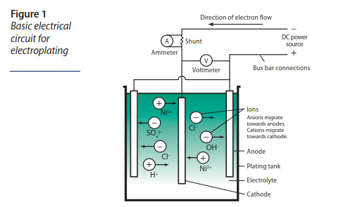
The part to be treated constitutes the cathode in the center, and the nickel is supplied by the two anodes on the outside.
This diagram and much of the information below is taken from the “Nickel Plating Handbook” document, see the Bibliography section below.
Literature gives us some interesting formulas. These formulas are very theoretical and assume high efficiency of the used solution. In the case of a home-made nickel acetate solution, this efficiency is probably not ideal, so all these figures are to be taken with precaution, nevertheless, the principles remain valid.
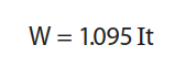
- W: amount of Nickel deposited at the cathode in Grams
- I: through current in Amps
- t: time in Hours
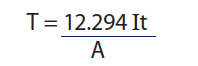
- T: Average thickness of the deposit in µm
- I: through current in Amps
- t: time in Hours
- A: covered area in dm²
The table above gives us an idea of the duration of the treatment to get a certain coating average thickness, depending on the current density, ie the number of Amps per unit area.
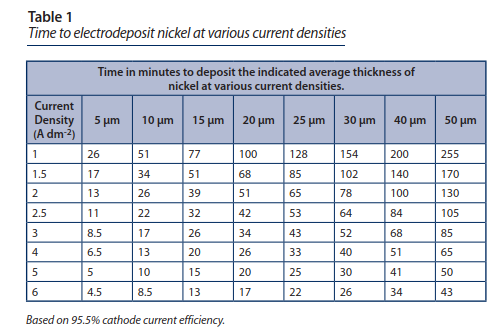
According to the sources, it seems that 3A / dm² (surface area of the part) is suitable. We also read that it is preferable that the voltage remains below 5V.
==> According to the table, at three Amps / dm², it takes 43 minutes to deposit 25µm.
In the case of my two pieces:
- Mando teledoline bridge: 0.63 dm * 0.63 dm * 2 sides = 0.8 dm² x 3 => Recommended current = 2.38A
- Teledoline potentiometer plate: 1 dm * 0.29 dm + pi .29²/4 * 2 faces = 0.7 dm² => Recommended current = 2.1 A
However:
The formation of hydrogen bubbles on the cathode affects the surface condition of the plating.
The higher the current, the more hydrogen there is.
The use of stirrers makes it possible to avoid sticky hydrogen bubbles and therefore the use of a stronger current.
If stirrers are not available, the recommendation is to take longer time and use low current.
You can use an aquarium bubbler as a stirrer.
The following figure explains the variations in thickness that can occur depending on part geometry.
The zones closest to the anodes receive more nickel atoms and are therefore thicker.
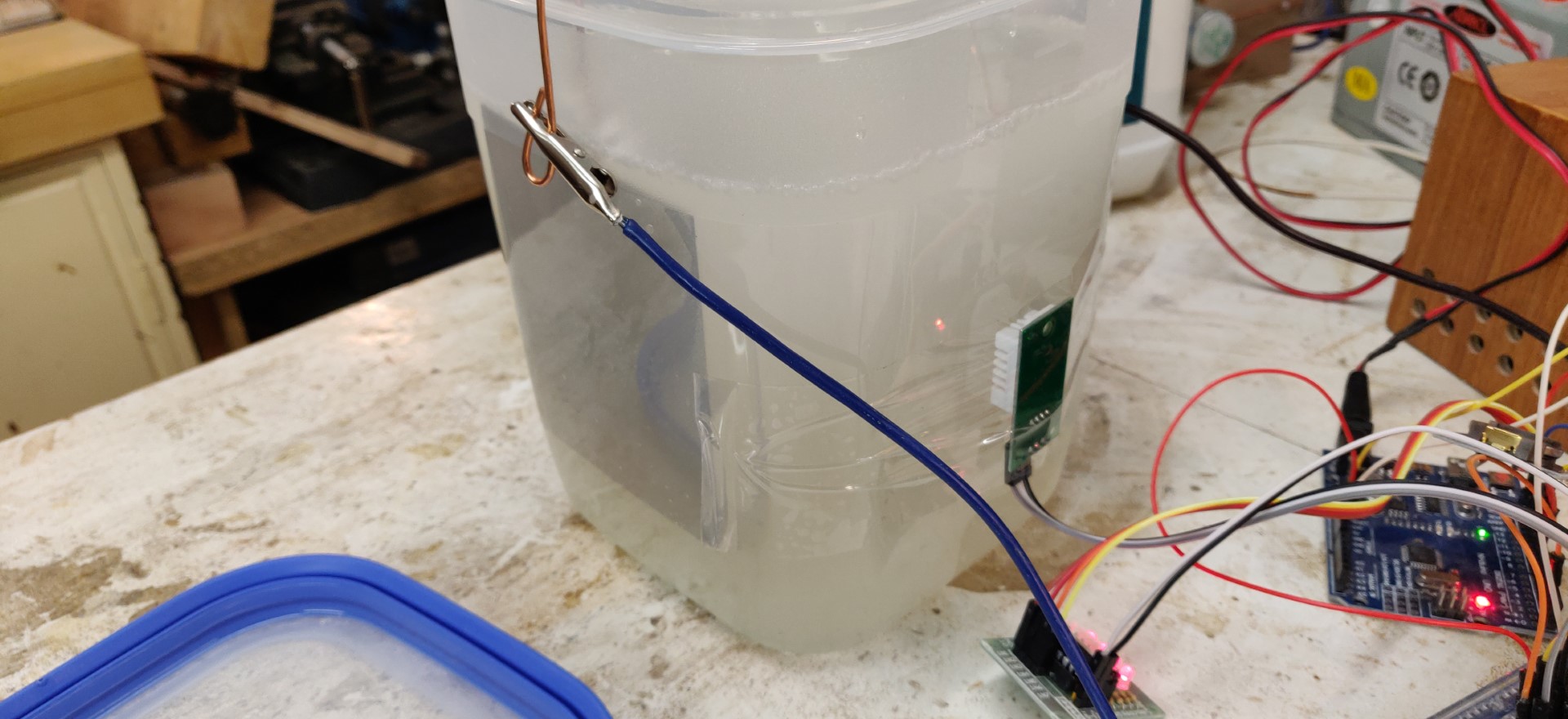
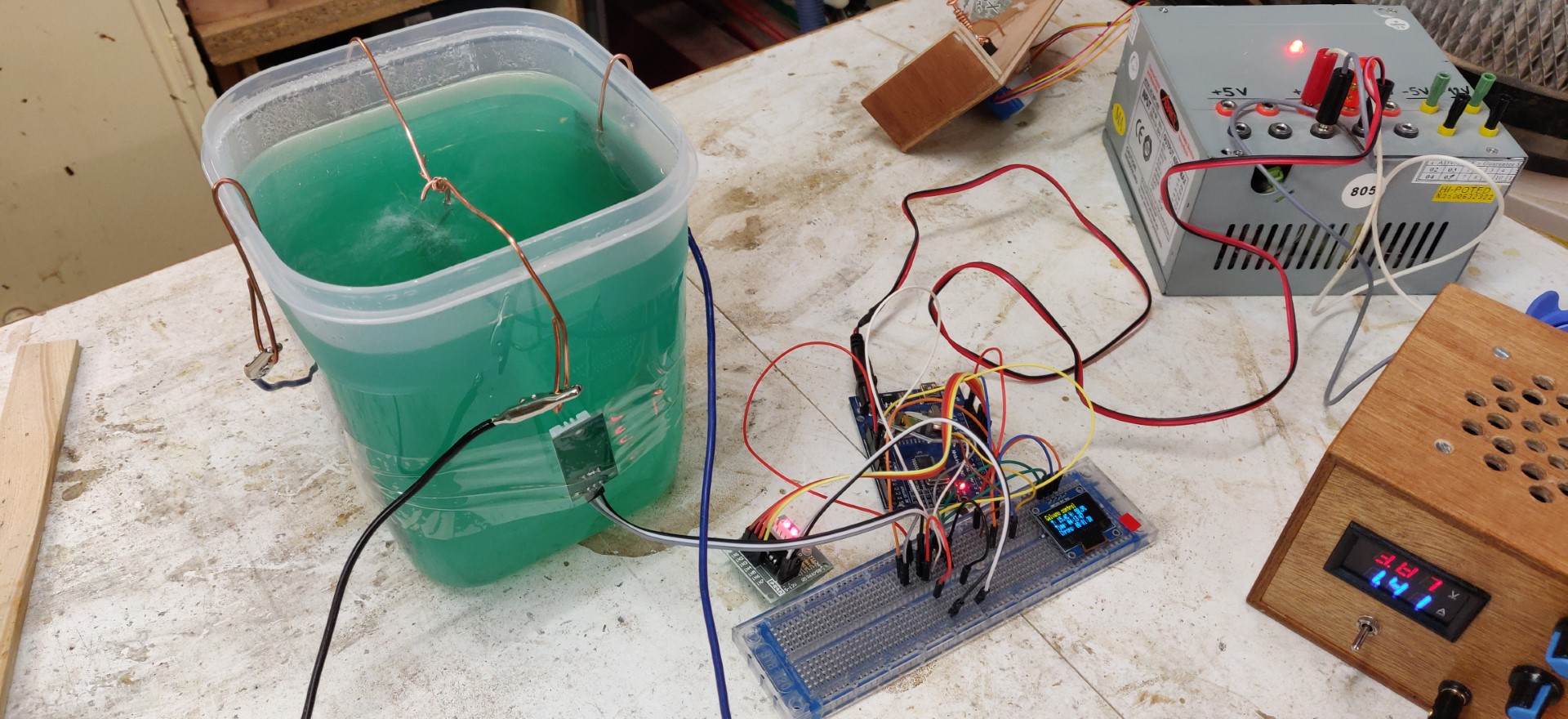
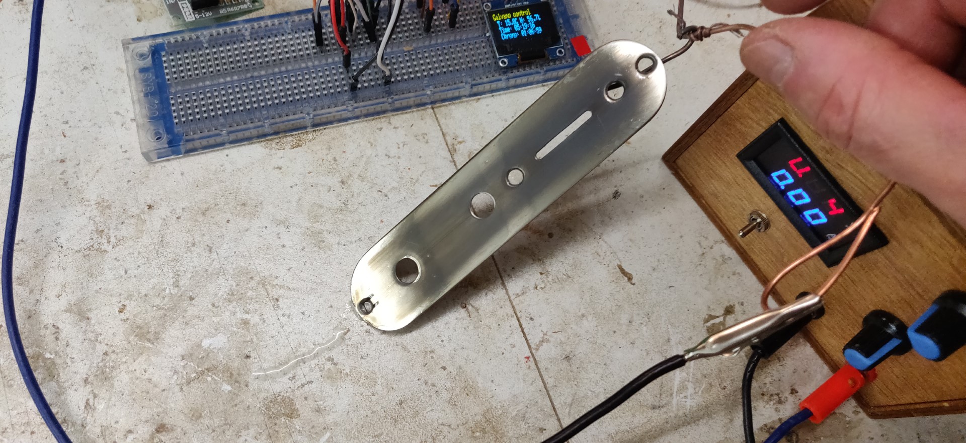
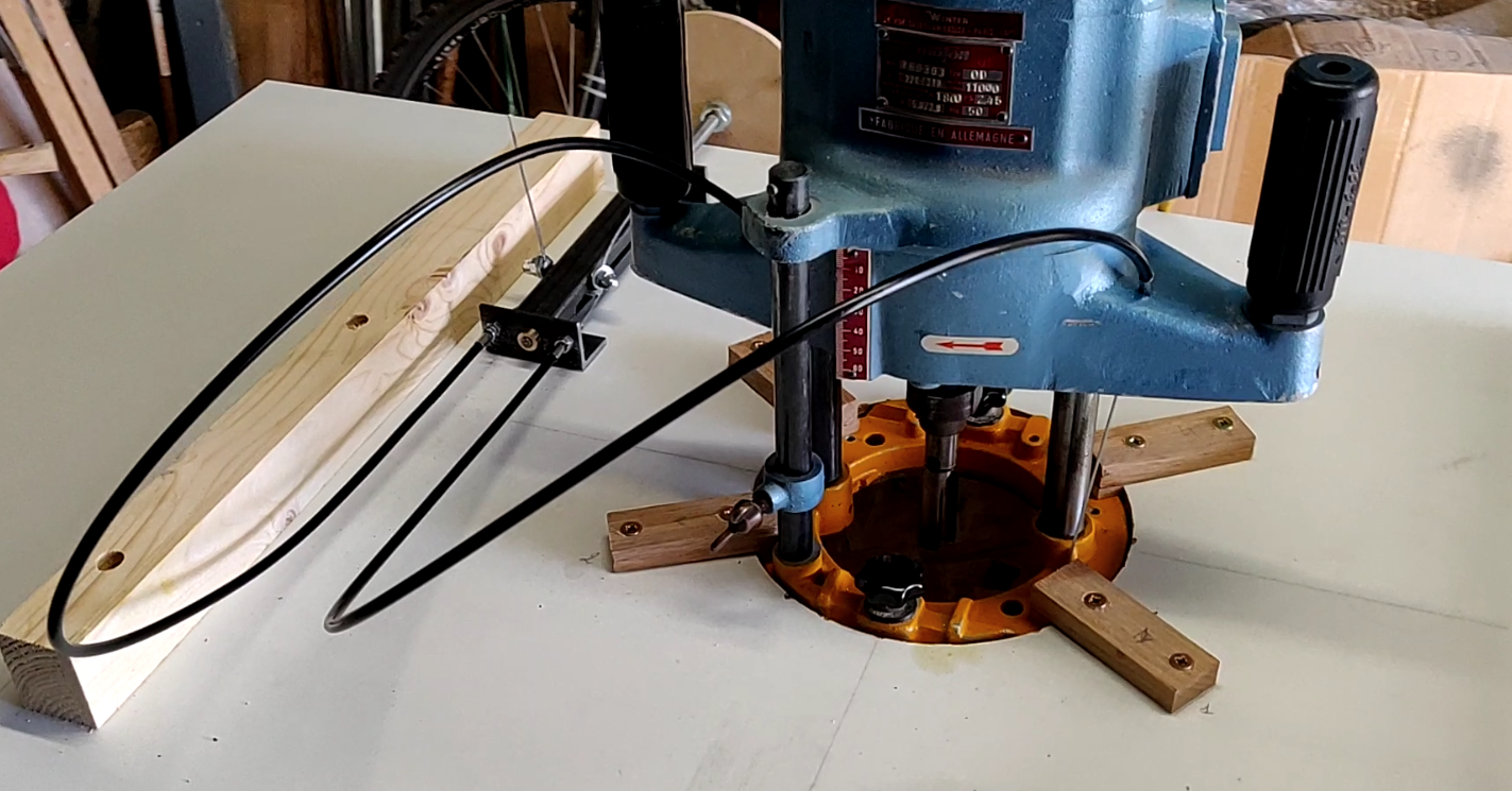
Practical setup
Immediately following rinsing with water, the part is immediately immersed in the electrolyte.
- For plating, the part is at the CATHODE, i.e. connected to the – of the power supply.
- Both Nickel plates on the right and on the left are ANODES, therefore the ++. It is interesting to have two or more anodes connected between
them, so as to face all the surfaces of the part.
For the reasons mentioned above, the power supply settings are much lower than for the electrolyte:
- 1A , or a little less,
- About 3V in my case.
The principle is not to go too fast because hydrogen bubbles can remain attached to the part and create irregularities.
It is useful to stir the part frequently during the operation to detach the bubbles.
It would have been better to use an aquarium bubbler to ensure permanent agitation in the bath,
unfortunately this time I didn’t have any on hand.
In my case, I got a satisfactory result after just over an hour.
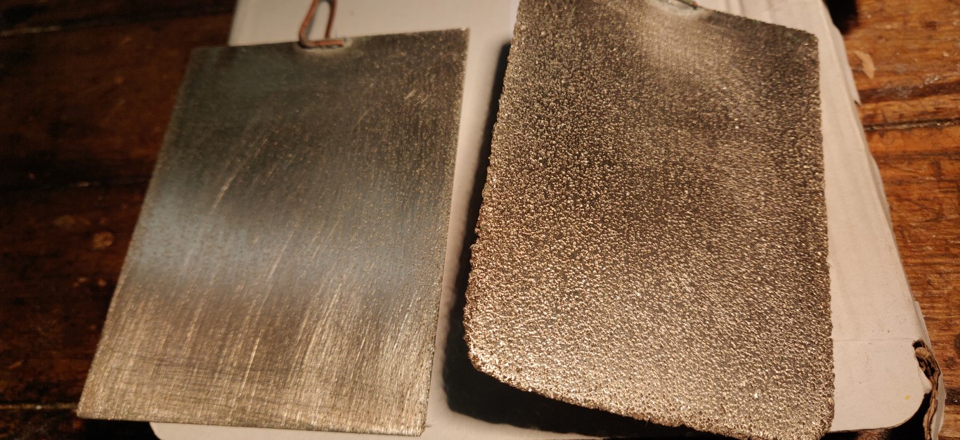
Polishing
After rinsing with clear water, polishing is carried out with a polishing compound for metals, not too abrasive. Polishing removes black marks corresponding to the rise of the bubbles towards the surface along the part. The layer is thick enough not to be afraid to go through, but I didn’t use any mechanical means.
Results

Bibliography
I refer you for more details to the publication “Nickel Plating Handbook - 2014” by the Nickel Institute which can be found here.

Older readers comments